We once saw a miswired system where a single panel dragged an entire array into inefficiency, despite an MPPT at the heart of the setup. MPPT controllers optimize energy harvest by matching panel voltage to battery voltage, but that requires careful panel compatibility, temperature tolerance, and aging effects. We’ll outline how panel specs drive MPPT performance and what sizing steps prevent losses, then address wiring, protection, and future expansion to keep your system efficient and safe.
Key Takeaways
- MPPT controllers optimize energy by matching panel voltage to the battery and load, improving efficiency over PWM under real-world conditions.
- Ensure panel array voltage stays within the MPPT controller’s input voltage range across temperature and shading variations.
- Check both Voc (cold) and Isc (high irradiance) to prevent controller limits being exceeded and to maintain safe operation.
- Align panel current capability with the controller’s maximum input current and duty-cycle range for stable and efficient transfer.
- Consider inverter compatibility and aging effects to preserve MPPT efficiency and avoid derating or suboptimal operation.
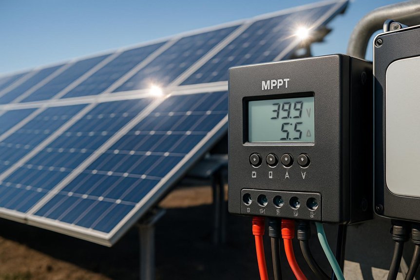
Why MPPT Matters for Your Solar Rig
MPPT controllers optimize the match between solar array voltage and battery voltage, extracting more usable energy than PWM controllers under real-world conditions. We approach this topic with a precision mindset: MPPT dynamically adjusts input to approach maximum power point, improving conversion efficiency across varying irradiance, temperatures, and panel configurations. This matters for long-term system performance, especially when array voltages drift due to aging or partial shading, where MPPT maintains higher voltage alignment and reduces losses. We also consider reliability: improved efficiency can reduce heat generation, potentially extending component life. When evaluating warranties, manufacturers often address panel aging and related performance degradation; understanding MPPT’s role helps anticipate warranty claims, distinguishing marginal losses from controller or panel faults. In sum, MPPT enhances energy yield, reliability, and claim clarity for durable solar rigs.
How Panel Specs Drive MPPT Performance
We’ll start by showing how panel voltage sets MPPT operating points and why DC-DC conversion efficiency hinges on staying near the maximum power point. We’ll examine current rating constraints to ensure the controller can handle surge or partial shading without clipping power. We’ll also address temperature effects on matching, noting how Vmp shifts with heat and why margins matter for reliable tracking.
Panel Voltage Impacts MPPT
Panel voltage directly shapes MPPT performance because the controller tracks the voltage at which the panel delivers maximum power. By aligning operating voltage to the panel’s max power point, we optimize mppt efficiency and minimize losses from IV curve deviations. This relationship is influenced by temperature, irradiance, and series resistance, which shift the MPP and require dynamic tracking. A higher panel voltage isn’t inherently better; it must match the controller’s input range and the system’s design to maintain stable operation. Proper voltage selection reduces transients, improves regulation, and sustains high mppt efficiency across conditions.
- Voltage alignment determines where MPP sits on the IV curve.
- Temperature and irradiance shifts demand responsive MPPT tracking.
- System design must keep panel voltage within controller’s optimal input.
Current Rating Constraints
Current rating constraints shape how MPPT controllers respond to the panel’s electrical limits. We analyze how the short-circuit current and maximum power current define the usable operating window, preventing current overshoot that could trigger protection or reduce efficiency. Our focus is on how panel efficiency interacts with current headroom in real-world conditions, including gusts of irradiance and partial shading, which shift the optimal operating point. We also consider inverter compatibility, since an MPPT that delivers excessive current can force the inverter’s input stage into suboptimal regions or trigger derating. By matching the panel’s current capability to the controller’s duty cycle range, we preserve efficiency, minimize losses, and maintain stable voltage and maximum power transfer across typical load and grid conditions.
Temperature Effects on Matching
Temperature changes shift a panel’s open-circuit voltage and, in turn, the MPPT’s operating point. We examine how temperature dependence alters matching between panels and controllers, affecting efficiency and real-world power. Our focus is on how spec shifts influence the MPPT’s ability to track the maximum power point under varying ambient conditions.
- Temperature dependence alters I-V curves, moving the MPP and demanding adaptive controller response.
- Panel material aging compounds these effects by changing resistance, voltage, and current characteristics over time.
- Accurate system design must account for worst-case temperature swings and aging to preserve safe, efficient operation.
We emphasize modeling the temperature-driven variability and implementing robust MPPT strategies to maintain optimal performance across panel vintages and environments.
How to Size Arrays for Your MPPT Controller

We’ll outline how to size arrays for MPPT by balancing panel array sizing, MPPT input requirements, and system voltage during setup. We compare current and short-circuit targets with the controller’s voltage window to avoid hit-or-miss operation. This framing sets a precise path for evaluating array configurations and ensuring stable, efficient performance.
Panel Array Sizing
How do we determine the right panel array size for an MPPT controller? We approach sizing with a precise balance of voltage, current, and safety margins, ensuring that the array operates near the controller’s optimum efficiency point. We account for panel efficiency, temperature effects, and shading management to prevent underutilization or overdrive. Our method uses datasheet specs, real-world irradiance, and MPPT tracking range to define a viable window for voltage and current. We then verify that short-circuit current does not exceed the controller’s input. The goal is predictable performance and long-term reliability.
- Define operating voltage and current ranges from the MPPT specifications.
- Apply conservative safety margins for temperature and aging.
- Integrate shading-aware layouts to preserve power yield.
MPPT Input Requirements
To size an MPPT input correctly, we start with the controller’s voltage and current operating envelope and guarantee the array can deliver within that window under worst-case conditions. We analyze the recommended MPPT voltage range and the maximum input current, then translate that into a realistic array configuration. We consider module Voc under cold conditions and Isc under irradiance peaks to ensure the operating point remains within the converter’s limits. We also address impedance matching and the impact of wiring losses on actual current at the controller. When dealing with disconnected arrays, we assess contingency scenarios where shading or partial shading may reduce output while still meeting minimum voltage. Wind resistance, though external, affects array exposure and thus feeder impedance, influencing effective voltage at the MPPT input.
System Voltage Balancing
1) Determine controller voltage window and module Vmp range, then size strings accordingly.
2) Use a mix of series strings and parallel groups to match current requirements without exceeding input limits.
3) Validate gains under varied irradiance and temperature to ensure consistent performance and cost-effectiveness.
Avoid Voltage Mismatches and Impedance Traps
Are voltage mismatches and impedance traps undermining your system’s efficiency, or are you overlooking how MPPT controllers negotiate real-world panels and batteries? We examine how misalignment between panel IV curves and battery voltage creates iffy operating points. MPPTs optimize by tracking maximum power along the system’s dynamic impedance, yet real panels exhibit series resistance, bypass diodes, and partial shading that generate impedance traps. These traps shift the DC operating point away from the true maximum power point, increasing misalignment losses. We quantify how controller input/output impedance, wire losses, and connector parasitics affect conversion efficiency. A disciplined approach aligns panel array voltages with battery chemistries, ensures compatible MPPT ranges, and minimizes impedance traps through cabling choices and solid interconnections.
Practical Steps to Size Panels and Controllers
Sizing panels and controllers boils down to matching real-world PV output to battery needs and MPPT range without wasting energy on overkill or under-sizing.
Sizing PV and controllers means aligning real-world PV output with battery needs and MPPT range for efficient, no-wuss oversize or undersize.
We focus on practical steps to sizing with clarity and precision:
- Assess daily energy demand, battery bank voltage, and MPPT input limits to define target current and power.
- Choose panel counts and configurations that stay within MPPT operating range while leaving headroom for shading and temperature.
- Plan for panel mounting and inverter pairing compatibility, ensuring mechanical fit and electrical harmony.
This approach minimizes losses, avoids overdesign, and supports predictable performance.
Note: The heading “panel mounting” and “inverter pairing” reflect integration considerations, not wiring or protection details.
Safe Wiring, Fusing, and Protection for Solar Rigs
What essential protections should we design into solar rigs to ensure safe, reliable operation? We implement safe wiring practices, correct conductor sizing, and rigorous protection basics. Fusing is mandatory at both input and output stages, sized to interrupt fault currents promptly. We separate positive and negative runs, maintain proper clearances, and shield cables from abrasion. Safety practices include proper enclosure grounding, signage, and timely diagnostic checks. We document amperage, voltage, and cable ratings to prevent overheating. In the table, we summarize key protections and their rationale.
| Protection Area | Rationale |
|---|---|
| Safe wiring | Reduces resistance heating and fault risk |
| Fusing | Rapid fault isolation prevents damage |
| Protection basics | Establishes baseline safety standards |
| Safety practices | Maintains ongoing operational integrity |
Plan for Growth: Future-Proof Your Solar System
Planning for growth starts with recognizing how protections from our prior discussion enable scalable expansion. We frame future-proofing around modularity, cost controls, and documented decision paths that support predictable performance. Our focus is on growth budgeting and warranty considerations, ensuring long‑term value without overcommitment. We assess component upgrade paths, MPPT controller headroom, and system cohesion to prevent bottlenecks as capacity increases. By codifying expectations, we reduce risk and improve maintenance cycles while preserving reliability.
1) Assess scalable architecture: module and controller interoperability, with clear upgrade routes.
2) Establish growth budgeting: staged investment, payback horizons, and contingency funds.
3) Flag warranty considerations: supplier coverage, in‑field serviceability, and documentation for future claims.
Frequently Asked Questions
How Do MPPT Controllers Handle Non-Standard Battery Chemistries?
We handle nonstandard chemistries by tailoring charge profiles and safety limits with precise monitoring; MPPT optimizes voltage/current for each chemistry, but two word discussion ideas: feasibility assessment. We assess risks, implement safeguards, and document results for readers.
Can I Mix Panel Brands Without Affecting MPPT Performance?
We can mix brands, but MPPT compatibility matters; we test gains, monitor temperature effects, and assess safety risks. We caution that non standard chemistries complicate performance, so we verify Voc and Isc tolerances before committing, ensuring safe, reliable operation.
What Testing Converts MPPT Gains Into Real Daily Energy?
We test daily energy gains by monitoring output across a full day, calibrating MPPT efficiency to reflect real conditions, including temperature and irradiance, then quantify improvements. We systematically compare data to ensure Testing daily energy gains meets expectations.
How Does Temperature Affect MPPT Efficiency and Voltage Setpoints?
How does temperature affect MPPT efficiency and voltage setpoints? Temperature impact shifts Vmp and Voc, altering setpoints; we must track ambient vs panel temp to maintain optimal current. We discuss, quantify, and adjust with precision. Do you follow?
Are There Safety Risks When Upgrading to Larger MPPT Controllers?
Upgrading safety can be managed, but we must respect controller ratings and wiring limits. We’ll verify voltage and current headroom, shielded terminations, proper fusing, and secure enclosure. We’ll photographically document changes for ongoing safety and compliance.
Conclusion
We balance precision with practicality, like pairing a caliper’s bite to a bolt’s thread. One side, ideal MPPT windows, voltage ranges, temperatures; the other, real-world aging, shading, and wiring losses. Juxtaposing perfect specs against imperfect deployments highlights where mismatches creep in—Voc too high, Isc overlooked, or impedance traps. By sizing thoughtfully and planning protection, we harvest reliability without overbuilding. In short: align panels and controller, then anticipate change to sustain efficient, future-ready solar rigs.

