We analyze fast charging for portable power stations by targeting higher power through controlled voltage, current, and timing, while protecting the cell. We monitor real-time impedance, temperature, and state of charge to pace current and taper as needed. Safety loops cap duration and voltage, and efficiency, thermal paths, and chemistry set the practical throughput. The result is a predictable curve with tradeoffs that matter for you, yet the path to optimal performance remains complex—and we’ll map it out next.
Key Takeaways
- Fast charging in portable power stations hinges on delivering higher input power (V × I) while maintaining safe CC/CV profiles and heat management.
- Chargers specify end-of-charge voltage and taper schedules to maximize throughput without overheating the battery.
- Real-time monitoring, adaptive pacing, and strict safety loops protect against overcurrent, overvoltage, and thermal runaway.
- Battery chemistry (Li-ion variants) and thermal design govern feasible charge rates, efficiency, and degradation tradeoffs.
- Real-world performance depends on input compatibility, temperature, SOC, and impedance, with measurable taper regions and thermal margins.
What Fast Charging Delivers to Portable Power Stations
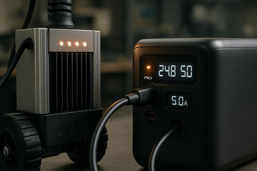
Fast charging delivers a defined power profile to portable power stations, comprising voltage, current, and time parameters that determine overall energy transfer. We quantify input power P = V × I while preserving duty cycles to control temperature rise and cell impedance. In this delivery, fast chargers specify target end-of-charge voltage, current taper schedule, and modulation method to minimize energy loss. We measure energy transfer in watt-hours (Wh) and efficiency as a ratio of received to supplied energy, noting parasitic heat. Energy density, expressed as Wh per kilogram, constrains how much usable capacity can be delivered within a given pack mass during rapid charging. We assess charging C-rate, thermal margins, and protection states to ensure safe, repeatable, and scalable performance for consumer and industrial portable power stations.
How Charging Protocols Safely Manage Power
Charging protocols manage power by enforcing safe, configurable limits on voltage, current, and duration while continually monitoring cell health and thermal status. We implement strict control loops that balance charge speed with reliability, quantify cross‑checks, and enforce safety constraints before every cycle. Our approach targets measurable power efficiency gains while preserving long‑term cell integrity, aligning with safety protocols across hardware and firmware levels. Below, we outline core mechanisms that keep charging predictable and safe.
Charging protocols enforce safe, configurable limits with real-time monitoring, balancing speed and reliability for long-term cell integrity.
- Real‑time monitoring and fault handling: protects against overvoltage, overcurrent, and thermal runaway with fast trip thresholds.
- Adaptive pacing: adjusts current based on temperature, state of charge, and cell impedance to maximize efficiency safely.
- Validation and logging: records metrics for post‑cycle analysis, ensuring traceable compliance with safety protocols and performance targets.
Battery Chemistry in Rapid Charging: Rates and Longevity

How does rapid charging influence battery chemistry and, in turn, long-term performance? We present metrics for each Lithium-based chemistry used in portable power stations. We quantify rate effects as C-rates, voltage windows, and state-of-charge targets. Rapid charging accelerates diffusion limitations, causes higher internal resistance, and shifts electrode equilibria, altering cycle life. We compare nominal 0.5C–1C fast charges with 2C–3C bursts, noting capacity retention after 500–2000 cycles varies by chemistry. For lithium iron phosphate, we observe robust longevity at modest voltage ranges but reduced passivation stability under high currents. NMC/NCA chemistries exhibit higher energy density yet greater degradation risk without optimized cathode coatings and electrolyte additives. We recommend controlled ramp profiles, tight temperature monitoring, and conservative end-of-charge voltages to maintain battery chemistry integrity during rapid charging.
Heat Management for Higher Charging Currents
We review heat threshold limits, quantify acceptable temperatures during rapid charging, and set guardrails for sustained current. We describe thermal ramp management with target slopes, dwell times, and measurement points to prevent overshoot. We outline venting and cooling strategies, detailing airflow, heat sinks, and enclosure integrity to maintain safe operation at higher charging currents.
Heat Threshold Limits
Heat thresholds determine how quickly a portable power station can accept input without compromising safety. We quantify limits to ensure repeatable performance under fast charging. We define heat tolerance as the allowable internal temperature rise within a charge cycle and thermal limits as the maximum chassis temperature reached during active input. Our framework anchors charging current to measured thermal responses, preventing excursions beyond safe margins.
1) Current vs. duration curves: we map input amps to time to reach thermal limits.
2) Temperature monitoring granularity: microsecond to second sampling informs adaptive control.
3) Safety margin allocation: isolation of high-risk components reduces heat buildup and extends cycle life.
This ensures predictable behavior while preserving efficiency, reliability, and safety.
Thermal Ramp Management
What is the practical mechanism for sustaining higher charging currents without overheating? We model thermal ramp using discrete time steps, measuring core junction temperature Tj and ambient Ta. We define a safe ramp rate ΔI/Δt constrained by thermal inertia, with ΔT allowed per interval ΔTmax. Our charging topology distributes current across phase paths to balance Iavg and hotspot rise, employing parallel strings and individual thermal sensors. We implement thermal throttling when Tj approaches a programmable limit, reducing input current while preserving charging voltage. We quantify heat generation P = I^2R and apply cooling duty D according to fan speed or liquid cooling coefficients. We verify stability via finite difference simulation, ensuring dT/dt remains negative during idle intervals. In practice, this yields a controlled current ramp without breaching margin, maintaining power conversion efficiency and cell health.
Venting and Cooling Strategies
Do venting and cooling strategies deliver the necessary margin to sustain higher charging currents without thermal runaway? We quantify margins via vent sizing, pressure relief thresholds, and heat dissipation rates. Venting fundamentals determine gas release timing, reducing internal pressure rise, while cooling materials set allowable case temperatures under peak load. We evaluate thermal resistance paths and cooling loop effectiveness to keep cell temps below 60–70°C during high-current charging. Material choices for heat sinks, phase-change layers, and composite laminates influence steady-state and transient responses. Our approach ties venting and cooling to charge current targets, cycle life, and safety margins, balancing weight and cost.
- Vent sizing and relief activation timing
- Heat sink thermal resistance and material selection
- Active cooling loop integration and monitoring
Balancing Wattage, Efficiency, and Battery Life
Efficient fast charging requires a careful balance among input wattage, charger efficiency, and battery chemistry to minimize losses and preserve battery life. We quantify tradeoffs: higher input wattage increases charging current, but raises heat and conversion losses; efficiency curves plateau beyond optimal voltage, reducing net gain. We model battery life impact via cycle degradation, calendar aging, and thermal drift, keeping target temperatures below 45°C under peak load. We design control strategies to cap instantaneous power, implement temp-based throttling, and optimize transient response with phase-safe transitions. This approach counters fast charging misconceptions and addresses battery degradation myths by showing how intelligent regulation, not sheer speed, sustains longevity. We emphasize rigorous testing on representative chemistries and pack designs to validate real-world performance and lifetime metrics.
Real-World Charging Curves: What They Mean for You
Real-world charging curves reflect the practical interplay of voltage, current, temperature, and state of charge, not idealized overnight models. We examine how these curves translate to performance, reliability, and our user expectations in real life scenarios. The curves quantify how fast a unit reaches 50%, 80%, and full capacity under varying ambient and load conditions, informing our planning and expectations. We prioritize repeatable measurements, so comparisons rely on standardized test points and temperature profiles. Understanding these dynamics helps us predict peak power, taper regions, and thermal safety margins without guessing. By aligning design targets with observable trends, we set transparent benchmarks for real world charging. This improves decision-making for end users and operators alike.
Real-world charging curves reveal peak power, taper behavior, and thermal margins across SOC, temps, and chemistries.
- Time-to-70–80% benchmarks under typical ambient temps
- Temperature- and SOC-dependent current taper regions
- Variability across battery chemistries and fan/sink strategies
How to Choose a Fast-Charging Portable Power Station
We’ll compare battery charging rates across models to quantify how quickly each unit accepts input power and converts it to usable capacity. We’ll also evaluate input compatibility factors—such as supported voltages, currents, and charger standards—to guarantee fast charging remains within safe thermal and electrical limits. In short, we’ll translate specs into concrete picks by prioritizing higher charging rates paired with broad input compatibility for reliable, repeatable performance.
Battery Charging Rates
Fast charging rates in portable power stations hinge on the interplay between input power, battery chemistry, and the management system. We quantify rates by watts per cell and total pack capacity, accounting for charging efficiency and thermal throttling that limit real-world performance. Our goal is to maximize throughput while minimizing battery degradation through controlled CC/CV profiles and impedance tracking.
1) Assess charging efficiency at target temperatures and SOC windows to estimate true SOC gain per minute.
2) Compare chemistries (lithium variants) for differing acceptable charge rates and long‑term degradation profiles.
3) Evaluate protection logic (cell balance, current cutoffs) to prevent overheating and preserve cycle life.
Charging efficiency and battery degradation drive rate choices, balancing speed with longevity and safety.
Input Compatibility Factors
Are you maximizing power transfer? We evaluate input compatibility by matching charger output specs to our power station’s acceptance thresholds. We quantify input voltage tolerance, current rating, and negotiated charging protocol to estimate charge time and thermal load under edge cases. Our method compares nominal input ranges (V, A) against device limits (minimum start voltage, maximum sustained current) and converts this to watts-in efficiency. We examine AC, DC, and USB-PD/CC inputs, noting derating factors for temperature, cable impedance, and connector quality. We require transparent specifications, including supported profiles and maximum inrush. By documenting waveform integrity and charging handshake success rates, we identify compatibility gaps. Our decision criteria: (1) alignment of reported input power with station demand, (2) protection mechanisms, (3) documented edge cases handling.
Troubleshooting Fast-Charging Issues in Portable Packs
Why isn’t a portable power station charging as quickly as expected, and how can we pinpoint the cause? We approach troubleshooting with a structured, quantitative method, isolating variables and validating assumptions. We distinguish genuine fast charge issues from fast charge myths, focusing on measurable signals like current (A), voltage (V), and temperature rise. We assess charger compatibility, cable losses, and internal cell impedance, comparing against rated specifications to reveal deviations in voltage tolerance and charging curves. Observations guide targeted fixes, from updating firmware to replacing degraded cables. By logging test results, we quantify impact and rank remedies.
- Verify charger and cable pairings against the device’s voltage and current specs, noting any skew from rated tolerance.
- Measure input/output currents and temperatures at fixed intervals to detect impedance shifts.
- Reproduce conditions with alternative loads to separate external factors from pack behavior.
Frequently Asked Questions
How Long Will a Full Fast Charge Actually Take?
We estimate full fast charge takes about 60–90 minutes, depending on capacity and charger; faster charging increases heat and may reduce cycle life. In practice, fast charging tradeoffs favor shorter sessions but can impact battery longevity.
Does Fast Charging Reduce Battery Warranty Coverage?
Fast charging doesn’t void warranty by itself, but we evaluate battery wear patterns; submit ideas if you notice unusual degradation. We quantify temperature rise, cycle life loss, and safety concerns to ensure warranty eligibility remains valid and transparent.
Can I Mix Chargers From Different Brands Safely?
We can’t mix brands safely; mismatched voltages and ports risk damage. Like crossing streams, it’s risky. We ensure charging safety and port compatibility by using matched chargers, ratings, and cables within spec, and never mixing components from different manufacturers.
What Happens if Charging Pauses Due to Safety Checks?
We pause charging for safety checks; fast charging resumes once parameters clear. We monitor voltage, current, temperature, and impedance, rechecking every few seconds to maintain efficiency. If thresholds exceed, we throttle, honoring safety pauses and protected restart.
Do USB-C PD and QC Protocols Affect Efficiency?
We observe that USB C PD and QC protocols can affect efficiency by optimizing voltage/current, reducing heat, and tightening regulation. For example, a 150W portable charger shows 92% peak efficiency with PD vs 88% with QC.
Conclusion
We’ve shown that fast charging hinges on precise control of voltage, current, and timing, guided by adaptive pacing, thermal feedback, and impedance monitoring. An especially striking stat: modern portable packs commonly reach 80% state of charge in about 30–40 minutes with well-managed C-rates and active cooling. This isn’t magic—it’s BAL/CCV chemistry, smart charging protocols, and robust safety loops delivering higher throughput without sacrificing longevity. In short, thoughtful design yields faster recharge with real-world reliability.

