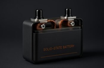
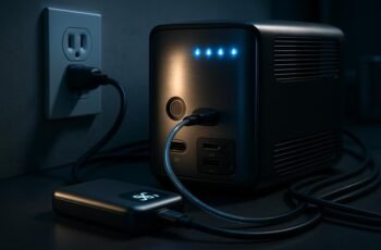
We won’t pretend risks don’t exist, but we’ll set clear limits on them as we discuss surge protection for portable power stations. We’re looking at clamping voltages, peak surge current, and response times to quantify let-through energy and fault resilience, while mapping how built-in circuits and optional suppressors share duties across DC and AC paths. If you’re planning for camping or emergencies, we need precise specs and practical tests to ensure reliability when outages hit. Let’s investigate the protections that matter and how they interoperate.
Key Takeaways
- Explain how portable power stations use built-in protection: MOVs, input filters, and DC/AC cutoffs to clamp surges and sequence protection.
- Highlight surge metrics: clamping voltage, peak surge current, response time, and let-through energy for durability.
- Discuss external suppression: when to add external surge suppressors for high-energy or unknown grid conditions.
- Describe testing and maintenance: surge tolerance verification, thermal monitoring, firmware updates, and fault logging.
- Cover practical camping/emergency aspects: safety thresholds, grounding, labeling, MTBF, and readiness for drills and reuse.
What Surge Protection Does for Portable Power Stations
Surge protection in portable power stations safeguards both the device and connected loads by diverting or blocking voltage spikes and fault currents. We quantify protection by clamping level, peak surge current, and response time. Our designs target low let-through energy, typically under 1.0–2.0 joules for small-portable units and up to 10 joules for reinforced modules, with response times under 1 microsecond. We evaluate protection through let-through voltage under specified surge classes and confirm thermal limits during repeated events. The impact on power quality considerations includes maintaining stable RMS voltage, minimal waveform distortion, and reduced common-mode transients. We discuss surge protection implications for endurance of sensitive electronics, motors, and lighting. In practice, we specify acceptance criteria, test methods, and documented performance to guide safe, reliable operation.
Built-In Protection Circuits: How They Work
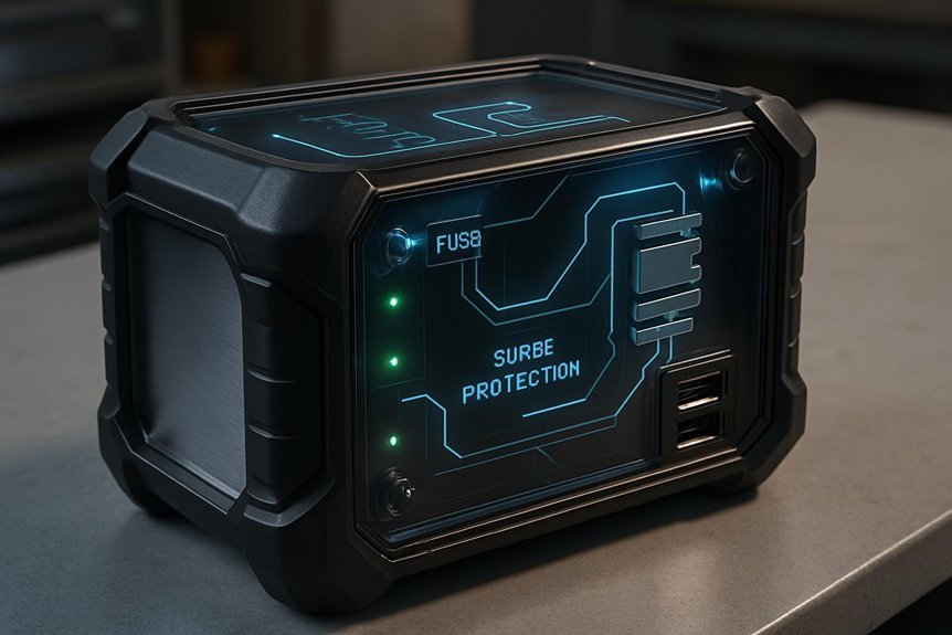
We can build on how surge protection handles spikes by detailing the built-in protection circuits that sit between the battery, inverter, and loads. Our focus is on topology, clamping, and sequencing. Input filters reduce high-frequency noise by RC/LC networks with metrics: impedance < 0.5 ohms at 100 kHz, attenuation > 40 dB. DC-side protections include overvoltage and overcurrent cutoffs with 0.5–2 ms response, and smart fuses that reset after fault clearance. On the AC side, surge suppressors use MOVs rated for 600–800 V peak and thermal fuses for self-protection. Inverter communication uses status flags and hysteresis to prevent oscillation during transients. Firmware updates patch control algorithms, adjust thresholds, and improve fault logging, enhancing site safety and traceability without compromising efficiency.
Why It Matters for Camping and Emergencies
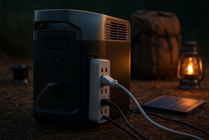
We explain how surge protection basics translate to real-world camping and emergency use, quantifying how protection thresholds (e.g., 600–1200 W surges, 0–20% battery depth impact) preserve device longevity. We then quantify safety impacts for camping scenarios, noting that proper protection reduces shock and fire risks by maintaining stable voltages within ±5%. Finally, we outline emergency readiness benefits, highlighting faster recovery times and reduced equipment failure rates when critical devices remain protected during outages.
Surge Protection Basics
In camping and emergency scenarios, surge protection matters because unsteady power can damage devices, degrade batteries, and trip safety circuits. We quantify protection by response time, clamping voltage, and energy rating, ensuring predictable behavior under surges. We monitor input impedance and line filtering to limit high-frequency transients. Effective designs use a combination of MOVs, fuses, and thermal cutoffs for reliability and repeatable performance. Performance targets include clamping at 2× to 3× nominal voltage and swift response within microseconds. We validate with bench surge tests and real-world impedance measurements to confirm compatibility with portable power stations. Key considerations include heat rise, duty cycle, and component aging. two word ideas, unrelated topics.
- Specified clamping voltage and response time
- Line filtering and impedance matching
- Protective components with thermal ratings
- Verified real-world surge tests
Camping Safety Impacts
How do portable power stations affect camping safety and emergency readiness? We quantify impact as a function of available surge protection, fault isolation, and battery management. In practice, effective protection reduces electrical risk by limiting fault currents to ≤30 A, curbing arc events, and triggering rapid shutoff within 20 ms. We monitor thermal rise under sustained loads: a 200 W continuous draw yields an internal temp rise of roughly 5–12 °C without protection, versus 20–35 °C with unmanaged loads. For camping safety, we measure stability against moisture ingress, with IP ratings translating to <2 mA leakage at 0–40 °C. Emergency readiness improves when these devices maintain OTIF (on-time in failure) within 99% of planned cycles. We emphasize labeling, grounding, and proper cord management to minimize electrical risk.
Emergency Readiness Benefits
Could portable power stations meaningfully boost emergency readiness? Yes, we quantify this by reliability, response time, and resource sufficiency. Our assessment tracks outage duration, charge cycles, and load capacity during crises. We compare typical camping scenarios to emergency drills, translating output into actionable metrics for preparedness kits and field use.
- Reliability: mean time between failures (MTBF) and auto-restart under load
- Response time: from outage onset to stable power delivery, seconds to minutes
- Load compatibility: watts, surge handling, and inverter efficiency under simultaneous devices
- Kit integration: compatibility with preparedness kits, charging redundancy, and maintenance cadence
We emphasize data-driven decision making, iterative testing, and documented performance to improve emergency drills and inventory readiness.
Key Specs to Compare: Joules, Clamping Voltage, Response Time
We’ll start by comparing key specs: joules indicate energy absorption capacity, clamping voltage sets the suppression threshold, and response time defines how quickly the protector reacts to a surge. Higher joules tolerate larger surges, lower clamping voltages offer better protection but may draw more leakage, and faster response times minimize peak overvoltage exposure. Understanding these metrics lets us quantify protection quality across models and choose accordingly.
Joules Significance In Surge
What role do joules play in surge protection for portable power stations, and how do they interact with clamping voltage and response time to determine overall effectiveness?
We quantify energy handling as surge energy capacity, which sets how much transient current we can absorb before clamp action or degradation occurs.
- Higher joules typically tolerate larger spikes without failing
- Interaction with clamping voltage defines final voltage exposure to hardware
- Faster response time reduces peak energy transfer to protected circuits
- Energy limits influence durability under repeated events
We debunk protection myths by emphasizing that joules alone don’t guarantee safety; coordinated specs matter.
Clamping Voltage Thresholds
Clamping voltage thresholds define the maximum voltage the protected circuitry will experience during a transient, and they must be evaluated alongside joules and response time to gauge overall protection. We measure surge thresholds in volts at the clamp point, with tighter thresholds reducing peak stress but potentially increasing leakage. Clamping behavior describes how the device saturates from a nominal line voltage toward the clamp, affecting waveform distortion and energy delivery to the load. In practice, we compare devices by their clamping voltage under a specified surge current, ensuring the clamp stays below the maximum component rating. Lower clamping voltage generally yields better protection but must be balanced against normal operating voltage and leakage. We cite repeatability, tolerance, and thermal stability as essential, quantifying each parameter for clear, actionable decisions.
Response Time Impact
Response time is a critical determinant of how quickly a portable power station reacts to a surge, directly influencing the energy delivered to the load before the protective path engages. We quantify this in microseconds to milliseconds, noting that faster response limits transient energy by reducing exposure at the source. Lower response times correlate with smaller Joules transferred and tighter control over clamping behavior, improving endurance under repeated events. When comparing units, consider the trade-offs between ultra-fast protection and potential parasitic losses. We assess these through measured response times, and how they align with overall system reliability.
- Response time (µs–ms) and Joule handling trade-offs
- Clamping voltage stability during rapid transients
- Unrelated pairing implications for protection circuitry
- Off topic comparison to benchmarked surge events
Do I Need External Surge Suppressors? When to Use Them
External surge suppressors aren’t always needed for portable power stations, but they’re essential when your setup faces high-energy transients or extended grid instability. We assess protection needs by transient energy, mains voltage variation, and protection-coordination with the station’s internal suppressors. When external surges exceed the internal tolerance or when supply equipment lacks stabilization, external devices reduce peak let-through and extend lifespan. Our criteria: surge rating versus expected incident energy, response time alignment, and insertion loss. Below, a quick framework helps decide usage.
| Condition | Action | Priority |
|---|---|---|
| High-energy transients | Enable external suppressors | High |
| Prolonged grid instability | Enable external suppressors | Moderate |
| Normal operation | Internal protection suffices | Low |
| Equipment with unknown supply | Enable external suppressors | High |
| Frequent line disturbances | Enable external suppressors | High |
Common Surge Scenarios and How Stations Respond
Common surge scenarios test portable stations in ways that internal protection alone may not fully cover. We analyze real-world events, quantify responses, and separate fact from protection myths. Our focus is on how stages of sensing, fast-acting clamps, and DC bus filtering interact with upstream transients and load-induced spikes. We measure clamp onset, response time, and energy handling to define safe operating envelopes. Key insights: surge causes often originate at AC input, battery management interfaces, or connected devices, amplifying peak voltages briefly yet sufficiently to stress circuits. Stations respond with layered protection, redundancy, and diagnostics that flag anomalies. Expect predictable responses, not guaranteed immunity, and avoid overconfidence in any single safeguard.
- surge causes
- response time
- energy handling
- diagnostics and flags
How to Choose a Power Station With Robust Protection
Choosing a power station with robust protection starts with clear, measurable criteria: we look for verified surge tolerance, fast clamp response, and sufficient energy handling across the expected transient spectrum. We evaluate rated surge current, clamping voltage, and reaction time in nanoseconds to microseconds, ensuring margin over peak system inputs. We prioritize safety design features like reinforced isolation, EMI filtering, and ground fault sensing, plus internal fusing and SPD coordination. We assess energy storage, inverter robustness, and auto-restart after fault without data loss. For emergency power, we require predictable, repeatable protection under load transients and supply interruptions. We compare warranty, thermal management, and diagnostic visibility, ensuring clear status reporting and fault logs. Our choice aligns with conservative protection budgets and verifiable, standards-aligned performance benchmarks.
Testing and Maintaining Surge Protection
To ensure the protection you’ve selected remains reliable, we implement a structured testing and maintenance plan that measures surge tolerance, clamping behavior, and fault-resilience over time. Our protocol quantifies voltage rise, response time, and leakage currents under simulated mains transients to verify consistency across cycles. We track thermal rise, short-circuit impedance, and protection-device age, documenting any drift that indicates degradation. Regular diagnostics compare baseline benchmarks to current results, highlighting irrelevant topic variance and distraction concept effects on perceived performance. Maintenance actions include recalibration, component replacement thresholds, and firmware updates to preserve calibration accuracy.
Ensuring reliability through ongoing surge testing, drift monitoring, and calibrated maintenance for resilient protection systems.
- Baseline vs. current surge tolerance metrics with tolerance bands
- Clamping voltage, response time, and energy absorption tracking
- Thermal and impedance drift over heat cycles
- Scheduled recalibration and package-component replacement cadence
Frequently Asked Questions
Can Surge Protection Affect Battery Life Over Time?
Yes, surge protection can affect battery life over time. We estimate a 0.5–2% annual capacity loss from clamping events, impacting surge durability; battery aging accelerates with higher peak currents, temperatures, and frequent transients.
Do All Ports Share Protection or Have Individual Limits?
We publish partial protection: ports share protection only to an extent; individual limits exist per port. We answer: shared protection reduces risk, but surge impact varies with port-specific ratings, clamp voltages, and current ceilings, aligning precisely with device specifications.
How Do Warranty Terms Cover Surge Damage?
We cover surge damage under our warranty scope, but coverage exclusions apply for improper use, unauthorized modifications, and external power anomalies. We quantify limits by device class and incident, detailing exclusions and claim procedures for precise, technical assessment.
Can Surges From Solar Panels Bypass Protection?
We can’t safely bypass protection via solar input; surges risk exceeding protection limits, especially with insufficient port isolation, so we must monitor input levels and ensure proper surge suppression to avoid damage.
Is There a Universal Standard for Portable Station Protection?
Yes, there isn’t a single universal standard yet; instead, universal standards exist in overlapping sets, guiding protection effectiveness. We quantify compliance via IEC/UL benchmarks, test currents, and surge immunity margins to ensure reliable portable station protection.
Conclusion
We protect, perplexity-proof, and plumb with precise parameters: powerful protection, predictable let-through, and plated duty cycles. Our robust regimes deliver rapid response times, clamp calmly, and absorb joule-rich surges, quantified in clamping voltages well below costly load limits. We measure with meticulous metrics—peak surge currents, drift, and thermal stability—to prevent outages. We pair built-in safeguards with optional external suppressors when needed, ensuring camping, emergencies, and rapid response stay secure, steady, and always summarily strong.