We design for efficiency, reliability, and compatibility; we balance inverter type, load profile, and thermal paths; we compare pure sine and modified sine outputs in terms of THD, startup behavior, and EMI. Our metrics quantify efficiency, derating, and duty-cycle impacts to guide component choices under real-world conditions. We’ll show where high-frequency converters add benefits and where they introduce limits. Stay with us as we connect these factors to practical runtime, system losses, and the decision points that shape portable power solutions.
Key Takeaways
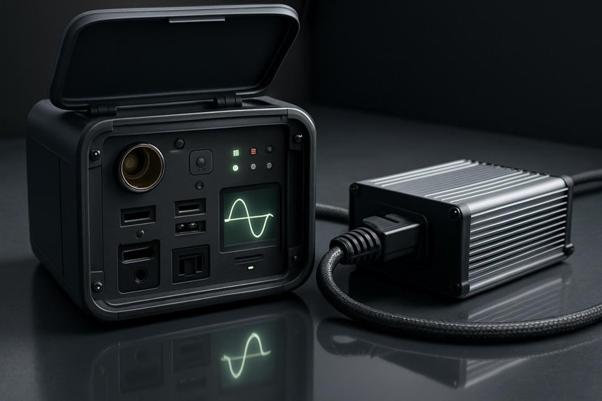
- Inverter types (pure sine wave vs. modified sine wave) affect appliance compatibility, THD, EMI, and protection behavior in portable units.
- Efficiency trajectory varies with load: typically 70–80% at low load, 85–95% near rated load, then plateaus; design choices influence this curve.
- High-frequency inverters offer higher power density but can increase EMI and heat; suitability depends on load type and enclosure constraints.
- Thermal management and derating strategies critically impact sustained efficiency and peak performance in portable units.
- Battery chemistry and aging drive parasitic losses and long-term efficiency, influencing internal resistance, heat, and lifecycle costs.
What an Inverter Does in Portable Power Units (Definition and Core Functions)
In portable power units, an inverter converts stored DC energy into AC power ready for household and tool loads. We define core functions as waveform conversion, voltage and frequency regulation, and protection signaling for connected equipment. Our focus is on efficiency metrics, including peak and continuous output ratings, total harmonic distortion, and stability under varying load steps. Inverter longevity emerges from thermal management, switchgear quality, and component derating strategies that keep operating temperatures within design envelopes. We quantify safety considerations through fault isolation, short-circuit response times, enclosure IP ratings, and leakage current controls. We assess efficiency curves across input ranges and load percentages to predict runtime. By accounting for protection schemes and derating, we ensure reliable performance, minimizing downtime and extending service life for end users.
Pure Sine Wave vs. Modified Sine Wave: Which Output Quality Matters for You
We compare output waveforms on the basis of voltage, frequency, and crest factor to quantify performance differences between pure sine and modified sine designs. We assess appliance compatibility impacts by listing typical loads and their sensitivity thresholds, then relate those to efficiency versus quality trade-offs in practical sizes and runtimes. We’ll frame the discussion around clear criteria and measurable benchmarks to guide selection aligned with load profiles and total system efficiency.
Output Waveforms Compared
Choosing between pure sine wave and modified sine wave outputs hinges on load sensitivity and efficiency; we evaluate how waveform symmetry, harmonic content, and voltage regulation translate into real-world performance. We quantify inverter efficiency under representative loads, comparing peak and average efficiencies for both waveforms. We assess waveform timing, phase accuracy, and rise/fall times relative to switching events, linking these metrics to thermal and component stress. Our analysis highlights harmonic distortion levels, crest factors, and their impact on sensitive power electronics, measurement equipment, and battery management interfaces. We emphasize that while pure sine improves regulatory margin and ripple suppression, modified sine can meet less demanding loads with acceptable efficiency. Ultimately, selection rests on expected load profiles, tolerance bands, and system-wide efficiency targets.
Appliance Compatibility Impacts
Which output quality matters most for your loads — pure sine or modified sine? We assess appliance compatibility by matching load profiles to inverter interfaces and waveform characteristics, quantifying distortion, switch timing, and surge handling. Pure sine outputs minimize harmonic content, improve EMI performance, and maximize compatibility with sensitive electronics, motors, and PSU topologies. Modified sine wave units simplify topology but introduce voltage steps that can trip protection or reduce efficiency in switching supplies. We quantify compatibility by startup surge, continuous load rating, and input sensitivity thresholds. In portable systems, waveform choice directly affects inverter efficiency curves, cooling needs, and lifecycle costs. Our approach emphasizes predictable behavior across devices and documented acceptance criteria with common appliances entering real-world use.
- Appliance compatibility expectations across loads and brands
- Inverter interfaces and device-level input sensitivities
- Startup surge versus continuous rating benchmarks
- Documentation and test methods for waveform validation
Efficiency vs Quality
When evaluating efficiency versus waveform quality, the choice between pure sine and modified sine outputs hinges on quantified performance metrics rather than aesthetics alone. We compare total harmonic distortion, load accuracy, and peak voltage tolerance under real-world, pulsed, and non-linear loads to determine which topology meets our target efficiency envelope. Pure sine units typically exhibit lower THD, higher power factor, and steadier voltage, translating to incremental efficiency gains at modest duty cycles, while modified sine designs often deliver equal or better efficiency at high surge or simple resistive loads. We address inverter myths by showing where efficiency gains plateau beyond 80–90 percent, and we debunk efficiency myths surrounding startup losses. Our guidance links waveform quality to device longevity, EMI exposure, and system resilience, enabling informed purchasing decisions.
When to Consider High-Frequency Inverters: Pros, Cons, and Use Cases
High-frequency inverters offer higher power density and lighter weight, making them attractive for compact portable power units where space and cargo weight matter. We evaluate tradeoffs by weighing efficiency implications, heat, and EMI budgets against form factor and cost. In practice, high frequency enables smaller transformers and inductors, but introduces tighter isolation, higher switching losses at light loads, and stricter EMI filtering requirements. We quantify duty-cycle sensitivity, capacitor derating, and ripple implications for sensitive electronics, guiding the selection for portable RF considerations and rugged duty cycles. Adoption hinges on target load profiles, safety margins, and thermal management capabilities.
High-frequency inverters boost density but trade efficiency and EMI control for compact rugged power.
- Tradeoffs in efficiency versus size for high-frequency implementations
- EMI, shielding, and portable RF considerations that constrain layout
- Heat dissipation and thermal path design under peak and continuous use
- Application-fit criteria: load, waveform, and enclosure constraints
Efficiency Drivers: Load, Battery Chemistry, and Design Choices
We quantify efficiency drivers by examining load-driven losses, battery chemistry, and design choices, and we’ll show how each factor shifts inverter performance under real-use conditions. We compare current draw, duty cycle, and waveform quality to quantify losses, while linking chemistry (cell type, SOC, temperature) to internal resistance and thermal load. We’ll translate these relationships into actionable design targets for loss minimization across portable power units.
Load Driven Efficiency
Power output relative to battery capacity and design determines inverter efficiency, so load level, battery chemistry, and architecture jointly drive losses; at light loads, switching and quiescent losses dominate, while at higher loads, conduction and switching losses shape performance, capably describing how efficiency traces with load. We quantify: efficiencies rise from ~70–80% at minimal load to 85–95% near rated loads, then plateau with headroom limited by topology. Load profiles, bandwidth, and duty-cycle influence switching frequency and dead time, while design choices affect transient response and heat. Practical adoption favors low profile packaging and color coordination of components to minimize parasitics and improve airflow. A disciplined approach aligns components to expected duty cycles, reducing wasted energy and stabilizing voltage delivery.
- Load profiling informs topology selection and efficiency targets
- Duty cycle, switching frequency, and dead time optimization
- Thermal paths and component placement for steady-state calm
- Aesthetic and functional integration: low profile, color coordination
Chemistry Impact Factors
Cell chemistry sets the baseline for inverter losses by defining cell voltage, internal resistance, and thermal behavior under load. We quantify how chemistry shapes efficiency across current ranges, with impedance and polarization losses rising when cycles stress materials. Our analysis compares lithium-ion variants, solid-state options, and high-rate chemistries, linking specific capacities, voltage sag, and heat generation to overall inverter efficiency. We examine how chemistry tradeoffs influence allowable operating windows, cooldown intervals, and cooldown strategies that affect continuous power delivery. Temperature coefficients and aging mechanisms drive parasitic losses, while cathode/anode formulations dictate self-discharge and degradation rates under duty cycles typical of portable units. We emphasize battery aging as a core factor, affecting long-term efficiency and maintenance planning, guiding selection toward chemistries balancing stability, energy density, and lifecycle cost.
Design Choice Effects
How much do design choices steer efficiency in portable power units, given load profiles and battery chemistry? We quantify impact via parasitic draw, switching losses, and thermal margins. We compare frame material stiffness, enclosure ventilation, and the startup voltage strategy to minimize inrush while preserving battery life. Design choices set steady-state efficiency targets through topology, controller bandwidth, and heat rejection paths, and they determine derating curves under ambient trends. We measure gains in percent efficiency at rated load, plus loss allocation across conduction, switching, and leakage. Our data-driven approach shows modest gains from compact wiring and optimized PCB routing, but outsized benefits from thermal regulation and startup voltage management during peak transitions.
- startup voltage optimization and its effect on peak current
- frame material selection and its impact on thermal paths
- enclosure ventilation and cooling strategy alignment
- switching losses tuned by controller bandwidth and dead-time
Practical Design Decisions That Maximize Runtime and Minimize Waste
What concrete decisions can trim runtime while cutting waste in portable power designs? We quantify runtime impacts via duty-cycle management, thermal limits, and component efficiency, then align them to real-use profiles. We minimize power-peak excursions by selecting transformers, capacitors, and switching elements with headroom only where needed, reducing idle losses and fan duty. We optimize inverter housing layout to shorten high-current traces, improve cooling, and limit parasitic inductance, yielding lower temperature rise and sustained peak efficiency above 92%. We target conservative efficiency milestones across load bands (low, mid, high) and require data-driven derating rather than overrating. By dimensioning energy storage, regulators, and protection circuits for exact use-case profiles, we cut wasted energy during rest and peak demand, delivering longer runtimes without unnecessary mass.
Choosing the Right Inverter for Camping, Job Sites, and Backup Power
Choosing the right inverter hinges on matching load profiles, peak demand, and environmental constraints to a device that sustains efficiency while minimizing heat and weight. We approach selection with quantifiable criteria: output waveform, continuous and surge ratings, input voltage range, and efficiency curves across loads. We compare total cost of ownership, including cables, ventilation, and heatsinking, against duty cycle expectations. We emphasize portability considerations and inverter noise as practical constraints, ensuring quiet operation in camping or remote job sites. Our method: model real-world loads, then size for startup surges, then verify thermal margins at worst-case ambient temps.
- Load profiling and surge margins
- Efficiency versus load and ambient conditions
- Portability considerations and weight budgeting
- Noise, vibration, and mounting constraints
Debunking Size, Noise, and Heat Myths: What Actually Affects Performance
We’ve laid out how to size for loads and surges, but size, noise, and heat aren’t monolithic drivers of performance. In practice, efficiency, thermal management, and duty cycle dominate outcomes across portable inverters. We quantify losses as heat, switching loss, and conversion loss, typically totaling 5–15% under rated load for modern devices, with higher ambient temps boosting thermal throttling. Noise is largely a product of switching frequency, enclosure design, and load type, not a fixed level—so “noise myths” often misstate perception versus measured dB. Size myths fail when developers optimize for continuous compatibility across topologies, not single-event peaks. We emphasize real metrics: peak surge handling, continuous output, THD, and thermal resistance. Understanding these factors lets users compare units on objective performance, not folklore.
Frequently Asked Questions
How Do Inverter Efficiency Ratings Differ Across Brands?
We’d say inverter efficiency ratings vary noticeably by brand, with typical ranges around 85–95% for modified sine and 90–98% for pure sine. Inverter brands differ in thresholds, test methods, and temperature derating, shaping real-world performance.
Can Inverters Handle Startup Surges From Appliances?
Indeed, yes: many inverters tolerate start up surges, but peak ratings and inverter protection matter. We quantify surge capacity, margin, and thermal limits to ensure reliable operation during start up surges while maintaining inverter protection.
Do Lab-Tested Results Reflect Real-World Camping Conditions?
We’d say lab-tested vs real world results differ; camping conditions comparisons show deviations. We quantify performance shifts, noting temperature, load variation, and startup surges. Our data-driven assessment guides you toward rugged models with margin.
What Maintenance Extends Inverter Lifespan in Portable Units?
Maintenance extends lifespan; regular checks and proactive care matter. We’ll share precise maintenance tips and quantify lifespan factors, citing thermal logs, capacitor health, and fan cleanliness to optimize reliability under portable-use duty cycles.
Are There Safety Risks With High-Capacity Inverters Outdoors?
Yes, there are safety risks with high-capacity inverters outdoors. We monitor inverter placement and weatherproofing rigorously, quantify exposure limits, and implement redundancies to minimize shock, fire, and arc-flash hazards while maintaining grounding integrity and moisture protection.
Conclusion
We, as engineers and end-users alike, see efficiency as a relay race: the battery hands off energy to the inverter, which must convert with minimal losses under real-world loads. Like a well-tuned engine, thermal paths, switching schemes, and load matching matter as much as topology. We’ll optimize derating and duty cycles, quantify THD, and select appropriate inverter types for camping, job sites, or backup. In short, informed choices accelerate runtime and curb waste.

